Component List
There were not many components needed for this circuit. We had two pairs of resisters with different values for each pair. The values for these resistors were calculated (calculations are shown later in the post). We had two NPN BC547 transistors. Two LED's (measured with a multimeter to be 1.7V). Lastly we had a PCB board. All these components were soldered onto a PCB board.
The Circuit & its Calculations

As you can see from the wiring diagram we have two separate circuits. One is the control side circuit and the other is the main LED circuit. Lets talk about the transistor. The transistor has three legs, the base leg (B), the collector leg (C) and the emitter leg (E). The transistor works like a relay. It needs a low amperage to open the gate for the high amperage flow. In this case when we supply current (amperage) to the base leg, the transistor will ground that circuit with the emitter leg, as the emitter leg is wired up on the ground side of the circuit. This will then open up the gate and connect the collector leg with the emitter leg. This will allow current to flow throw the LED as the circuit is now grounded. Now as you know different components require different amount of current to operate. Using the data sheet we found out that the saturation current flow for the base side of the transistor was 0.5mA (0.005A). The base side of the transistor circuit has a 5V power supply and a resistor. The value of the resistor had to be calculated using ohms law (R = V/I). So my calculation to find out the resistor value was 4.4V divide by 0.005A. This equaled to 880Ohms. So the resistor value is 880Ohms. The reason why I used 4.4V and not 5V is because the base side of the transistor uses up 0.6V to turn on and therefore the voltage available to the circuit is 4.4V and not 5V. Now lets find out the resistor values for the LED circuit. We were given the current required by the LED to operate. It was 20mA (0.02A). The power supply on the LED circuit was 12V. But we got to keep in mind that the LED requires 1.8V to turn on and the collector side of the transistor requires about 0.2V to turn on. This means that the voltage available to the circuit is 10V. We use the same formula as above to calculate the resistance (R = V/I). My calculation was 10V divided by 0.02A, which equaled to 500ohms. The resistor values are 500ohms.
The Two Laws Relating To This Circuit
Ohms Law:
"Ohms Law states that the current through a conductor between two points is directly proportional to the potential difference across the two points, and inversely proportional to the resistance between them." (Wikipedia quote) The formula for this is I = V/R. This formula can be rearranged to find any of the values as long as you know two of them.
Kirchhoff's Law:
Kirchhoff's Law states that the voltage supplied to a circuit is used up within the circuit before it reaches back to the power source (ground). Voltage supplied = Voltage used by the circuit.
Breadboard Circuit Test
Before we were allowed to make our circuit on the PCB board we had to first prove that it actually works. That's why we first build our circuit on a breadboard to see whether it actually works. This is when i encountered my first problem. The class didn't have the exact value of the resistors i needed so therefore i had to compromise. Instead of a 500ohm resister and a 880Ohm resister, i was supplied with a 470ohm resister and a 800ohm resister. This meant i had to re-calculate my current readings. The 30ohm difference from 500ohms to 470ohms only made a difference of plus 0.1mA. This meant that my LED was now going to receive 0.021A instead of 0.02A. This was a very small change and therefore was nothing to worry about. The calculation was 10V divided by 470ohms, which equaled to 0.021 (formula used was I = V/R). The same calculations were carried out for the 880ohms resistor to the 800ohms resistor. The calculation was 4.4V divided by 800ohms, which equaled to 0.0055A. The lower resistance added 0.05mA to the current flow. This change would not make a difference as it is too small to cause any damage. Also the saturation value means what is the minimum current required to turn the base side of the transistor fully on. That means a little more current is fine and wont cause any harm to the transistor.

PCB Board
Once we proved that our circuit works on the breadboard we were allowed to make it for real on the PCB board. The PCB board is something that we haven't used before. It has rows of holes where you components can sit into and all the holes on each row are connected together (but row to row are not connected). This is why we had to put cuts in the rows to stop it from connecting to all the components. The purpose of the PCB board is for us to use these rows and and make a circuit and not use wires. Before we could lay out our components on the PCB board we had to plan it on the computer, using a program called LochMaster. This program allows you to place your components any way you want and it then allows you to check for continuity between each component. If say my resister and LED were connected together (had continuity between them), both of them would then receive 10V power supply and the voltage wont be shared. This is why we put cuts in between the components (middle of my resister and in the middle of my LED).

After our design was checked and ticked off we were allowed to place the components on the PCB board and solder the components down. When we solder the solder has to be small and shinny. A dull soldering represents a bad connection and it wont have a long life. I encountered my second problem while soldering. I bridged two components together, creating a short circuit. This would mean that my LED's wouldn't turn on and the circuit wont work. To fix this problem was easy. I used the soldering iron to break the solder in between the two components to unbridged them. This technique was showed to me by Vijay, my tutor.
Here is the pictures of my completed task

This is the frontal view
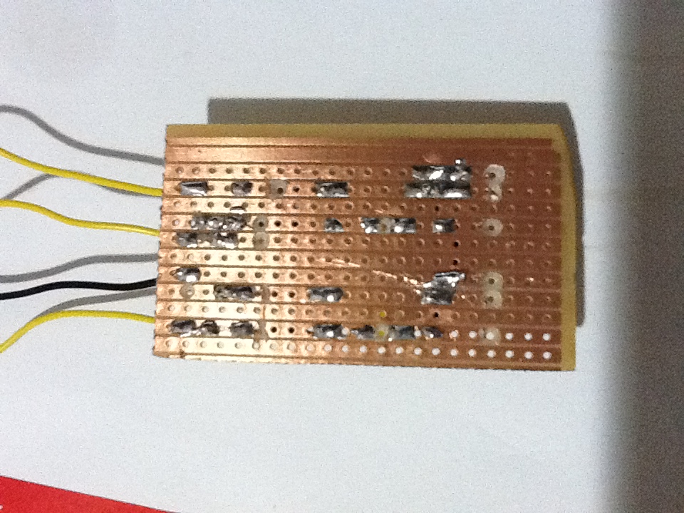
This is the backside view
Problems & Reflection
My main problem in completing this task was soldering. I just couldn't do a good joint soldering. My soldering sometimes even bridged two components together creating a short circuit. This was fixed as explained above. Soldering a component can be the thin line between a good connection and a bad connection. A good connection will have little solder. It will be covering the whole leg and it will be shinny. A bad connection will be having lumps of dull solder that don't even cover the entire surface of the components leg. If given the opportunity i would improve my soldering skills by practicing on a dummy PCB board. This will improve my soldering skills and it will result into a better joint connection. A bad connection can also cause resistance in the circuit. This resistance can create restriction to current flow. This will mean that the circuit will now experience a lower current flow and the voltage available to components will also decrease by a small amount, as this voltage is now required to push the current through this bad connection. This will not make much difference to the circuit but it can corrupt the circuit readings. This is why it is vital to have good connections.
very good Jal, keep it up
ReplyDelete